2019年6月5日 星期三

Verilog Edge vs. Level, Blocking vs. non-Blocking

edge_blocking


// edge 觸發 會生成 clock 和 flip-flop
// 中間過程的 blocking 運算都循序運行並即刻得出最後的結果
// blocking 的模式表示所有的運算步驟都會在這次 clock tick 之內完成

module edge_blocking(
input clk, x, 
output y);
reg a, b, c, d, e;
assign y = e;
always @ (posedge clk) 
begin
a = x;
b = a;
c = b;
d = c;
e = d; 
end
endmodule


edge_non_blocking
// edge 觸發 會生成 clock 和 flip-flop
// 中間過程的 non-blocking 運算會循序串聯
// 每個 clock 的 edge 會同時對 "<=" 右邊的symbols取值,並賦予"<=" 左邊的 symbols.
// 所以 non-blocking 模式 其實是一種 parallel 模式
// 特徵是 共用一個 clock 訊號,所以一個 tick 只能作動一次

module edge_non_blocking(
input clk, x, 
output y);
reg a, b, c, d, e;
assign y = e;
always @ (posedge clk) 
begin
a <= x;
b <= a;
c <= b;
d <= c;
e <= d; 
end
endmodule


edge_blocking_non_blocking
//  中間 b = a 的 blocking 指令被當作 組合邏輯 短路跳過了
module edge_blocking_non_blocking(
input clk, x, 
output y);
reg a, b, c, d, e;
assign y = e;
always @ (posedge clk) 
begin
a <= x;
b = a;  
c <= b;
d <= c;
e <= d; 
end
endmodule


edge_blocking_non_blocking (2)
module edge_blocking_non_blocking(
input clk, x, 
output y);
reg a, b, c, d, e;
assign y = e;
always @ (posedge clk) 
begin
a <= x;
b = a + 1'b1;
c <= b;
d <= c;
e <= d; 
end
endmodule


level_non_blocking
// level 觸發 不會生成 clock 和 flip-flop
// 中間過程的 non-blocking 運算其實和 blocking 運算 並無差別 
// 等同於 對 wire 做 assign 的效果,是一種組合邏輯的方式
// level 的觸發方式之下,使用 non-blocking 和 blocking 並無差別
// non-blocking 只對於 flip-flop 這種有記憶性,有時間差的線路 才有意義
// 對於 level觸發的 組合邏輯線路,無法做到 non-blocking
// blocking vs. non-blocking 的說法是有點誤導的,應該說是 sequential vs. parallel.
// level 觸發 一律使用 sequential (blocking) 的模式
// edge 觸發 才會使用 clock 和 flip-flop,才會需要區分  sequential (blocking)  和 parallel (non-blocking) 模式。
// 

module level_non_blocking(
input clk, x, 
output y);
reg a, b, c, d, e;
assign y = e;
always @ (*) 
begin
a <= x;
b <= a;
c <= b;
d <= c;
e <= d; 
end
endmodule


level_blocking
module level_blocking(
input clk, x, 
output y);
reg a, b, c, d, e;
assign y = e;
always @ (*) 
begin
a = x;
b = a;
c = b;
d = c;
e = d; 
end
endmodule


level_mixed
// 因為只有對 clk sensitive,所以 clk 會有 latch 的作用
// clk 是 level sensitive ,所以不是使用 flip-flop 的方式製作,而是使用 latch 的模式

module level_mixed(
input Din, clk,
output s3);

reg s1, s2;

always @ (clk)
if (clk)
begin
s1 <= Din;
s2 = s1;
s3 <= s2;
end
endmodule


level_mixed - 2
// 因為只有對 clk sensitive,所以 clk 會有 latch 的作用
// clk 是 level sensitive ,所以不是使用 flip-flop 的方式製作,而是使用 latch 的模式

module level_mixed(
input Din, clk,
output s3);

reg s1, s2;

always @ (clk)
if (clk)
begin
s1 <= Din;
s2 <= s1;
s3 <= s2;
end
endmodule


2019年4月3日 星期三

Bridges - Pretend your PC a Raspberry Pi or an ESP32 to connect I2C/SPI/GPIO/UART peripherals

Grand Island bridges


Wei Lin
2019-4-2

[Usage Scenarios]

Read on if these scenarios suit you:

[Motivations]

  • Need to use some I2C/SPI/GPIO/UART interfaced device with my PC:    
    • One of my Python projects needs to use a SPI-interfaced device.     
    • However, there is no external SPI interface available on the PC, therefore comes the bus-converter.
  • Bus-Converters selection:
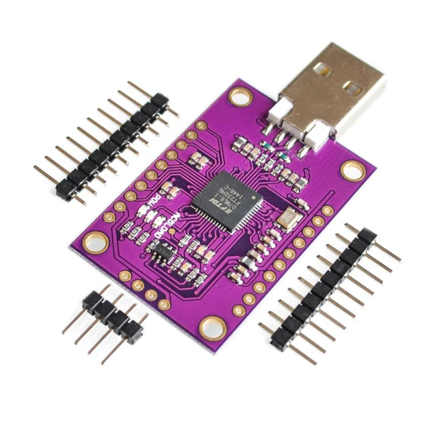
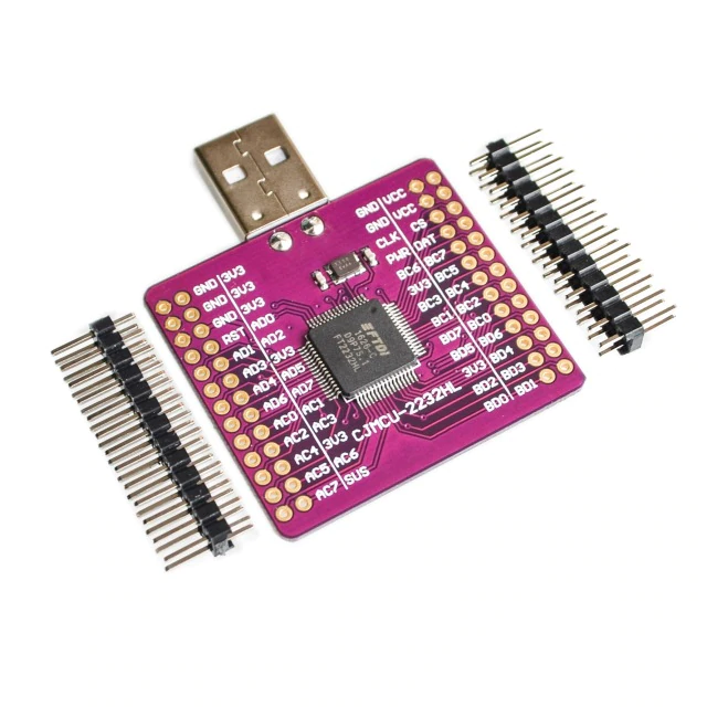
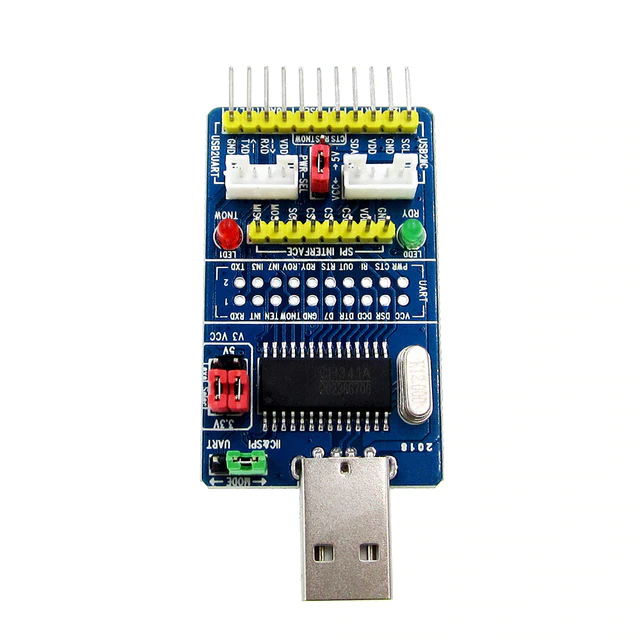
    • There are many USB to I2C/SPI/GPIO/UART converters available on the market. FT232H (1 channel) / FT2232H (2 channels) from FTDI and CH341 from WCH ... is popular. FTDI's documentation and development resources are quite complete and relatively easy to develop.     
    • PyFtdi was chosen to drive FTDI chips, it only depends on PyUSB. In addition, we nee also...
  • Drivers for the device:     
  • Requires Adapters to convert interfaces:     
  • Pretend your PC an ESP8266 / ESP32 / Raspberry Pi:     
    • As long as the device driver can run on a PC, and the SPI interface object it faces has exactly the same behavior of the SPI interface object on the ESP32, then the PC "IS" an ESP32 to the device driver. So in this cases, PC is an ESP32 simulator, at least to the device driver. So, we can...
  • Utilize powerful development resources and debugging environment from PC:    
    • For example, when developing a device driver, you can use PyCharm to set breakpoints and to inspect variables whenever needed. 
    • No more "print" to debug, no more repeatedly uploading code to the controller.
FT232HFT2232HCH341A

[Goals and Features]

  • Writing a package to simulate the I2C/SPI/GPIO/UART interface objects for MicroPython+ESP8266/ESP32 and Raspberry Pi on PC:
    • Interface objects in MicroPython + ESP8266 / ESP32 environment:
      • machine.I2C
      • machine.SPI
      • machine.Pin
      • machine.UART
    • Interface objects in the Raspberry Pi environment:
      • smbus2.SMbus
      • spidev.SpiDev
      • RPi.GPIO
      • PySerial.Serial
  • Can drive many bus-converters simultaneously:
    • Multiple bus-converters can be connected at the same time, and the number is limited only by the specification of USB and power supply capability.
  • Can function under Windows / Linux:
    • No modification is required.
  • Can be used on PC / Raspberry Pi or any machines that can run PyFtdi package:
    • No modification is required.

[How to use]

Simulating for MicroPython + ESP8266 / ESP32

# On ESP32 with MicroPython
from machine import I2C

i2c = I2C(freq = 400000)

# On PC
from bridges.ftdi.controllers.i2c import I2cController
I2C = I2cController().I2C

i2c = I2C(freq = 400000)

    
# On ESP32 with MicroPython
from machine import SPI

spi = SPI(id, baudrate = 10000000, polarity = 0, phase = 0)
spi.init()

# On PC
from bridges.ftdi.controllers.spi import SpiController
SPI = SpiController().SPI

spi = SPI(id, baudrate = 10000000, polarity = 0, phase = 0)
spi.init()
     
# On ESP32 with MicroPython
from machine import Pin

p0 = Pin(0, Pin.OUT)
p0.value(0)
p0.value(1)

p2 = Pin(2, Pin.IN, Pin.PULL_UP)
Print(p2.value())

# On PC
from bridges.interfaces.micropython.machine import Pin
from bridges.ftdi.controllers.gpio import GpioController
machine = GpioController()

p0 = machine.Pin(0, mode = Pin.OUT) 
p0.value(0)
p0.value(1)

p2 = Pin(2, Pin.IN, Pin.PULL_UP)
Print(p2.value())
  
# On ESP32 with MicroPython
from machine import UART

uart = UART(1, 9600)
uart.init(9600, bits=8, parity=None, stop=1)

# On PC
from bridges.ftdi.controllers.uart import UartController
UART = UartController().UART

uart = UART(1, 9600)
uart.init(9600, bits=8, parity=None, stop=1)

Simulating for Raspberry Pi

# On Raspberry
from smbus2 import SMBus 

bus = SMBus(1)
b = bus.read_byte_data(80, 0)
print(b) 

# On PC
from bridges.ftdi.controllers.i2c import I2cController
SMBus = I2cController().SMBus

bus = SMBus(1)  # the bus number actually doesn't matter.
b = bus.read_byte_data(80, 0)
print(b) 
# On Raspberry
import spidev

spi = spidev.SpiDev()
spi.open(bus, device)
to_send = [0x01, 0x02, 0x03]
spi.xfer(to_send)

# On PC 
from bridges.ftdi.controllers.spi import SpiController
spidev = SpiController() 

spi = spidev.SpiDev()
spi.open(bus, device)
to_send = [0x01, 0x02, 0x03]
spi.xfer(to_send)

# On Raspberry
import RPi.GPIO as GPIO

GPIO.setmode(GPIO.BOARD) 
GPIO.setup(6, GPIO.OUT)

# On PC
from bridges.ftdi.adapters.rpi.RPi import GPIO 

GPIO.setmode(GPIO.BOARD)  # mode actuall doesn't matter.
GPIO.setup(6, GPIO.OUT)

# On Raspberry
import serial
ser = serial.Serial('/dev/ttyUSB0') 

print(ser.name)        
ser.write(b'hello')     
ser.close()            

# On PC
from bridges.ftdi.controllers.uart import UartController
ser = UartController().Serial() 

print(ser.name)        
ser.write(b'hello')     
ser.close()      

[Test results]

  • Breakpoints and variables inspection 


  • Transceive LoRa packages directly from your laptop 


Notes

  • Mainly supports FTDI chips for now.
    • For CH341A:
      • Only I2C and GPIO functions are implemented, no SPI.
      • UART can be driven directly with the driver from WCH.
  • FTDI chip limitations
    • No IRQ.
      • The FT232H/FT2232H does not have endpoint of "interrupt input" type, IRQ functionality can only achieved with polling, which is too CPU intensive.
    • No PWM. PyFtdi, FT232H/FT2232H doesn't support.
    • In the same channel, the functionality of GPIO can coexist with SPI, but not with I2C/UART.
    • GPIO has no pull-up / pull-down functions.

References

Bridges - 讓 PC 像 Raspberry Pi 或 ESP32 一樣 連接 I2C / SPI / GPIO / UART 週邊裝置

Wei Lin
2019-4-2

[使用情境]

先說說 使用情境,合用的話再往下看:

[緣由]

  • 需要使用PC 直接連接 I2C/SPI/GPIO/UART介面的周邊裝置:
    • 最初是因為手上的一個 Python 專案,必須連接上某個 SPI 介面的裝置抓取資料來計算。
    • PC環境下的 運算能量,與強大的 Python套件資源,可以做到一些在 MicroPython + ESP32 甚至 Raspberry Pi 上無法做到的事情。
    • 但是因為 PC 上並沒有 外接的SPI介面 可供連接,必須透過轉換器。
  • 轉換器 的選擇:
    • 市面上有很多種 USB to I2C/SPI/GPIO/UART 的轉換器,常見的有 FTDI 的 FT232H (1 channel) / FT2232H (2 channels) 和 WCH 的 CH341...等數種。 FTDI 的文件與開發資源相當齊全,開發上相對容易一些。
    • 已經有很多 libraries/套件 可以用來驅動 FTDI 的晶片,但考慮跨平台的可攜性,最後選擇使用 PyFtdi,它透過 PyUSB 下達指令給 FTDI 晶片,相依的中間曾套件比較少一點。另外我們還...
  • 需要 裝置的驅動程式:
    • 可以透過 FT232H/FT2232H,與 I2C/SPI/GPIO/UART 的週邊裝置溝通,但是另外還需要 裝置專屬的驅動程式。例如要驅動 OLED display,就需要 SSD1306 (顯示面板控制 IC)的驅動程式
    • 這些針對性的驅動程式 普遍地存在於 ESP8266 / ESP32 / Raspberry Pi 的生態圈中,許多是使用 (Mico)Python 撰寫的,有些不須修改,或者經過少許修改,就可以直接在 PC 上執行,因此可能可以重複利用,不須重新開發,但是...
  • 需要 Adapters 來轉換介面:
  • 將 PC 視同是 ESP8266 / ESP32 / Raspberry Pi:
    • 如果裝置的驅動程式可以在PC上執行,而它所面對的 SPI介面物件,行為上和 ESP32上的SPI介面物件 一模一樣,那麼對 裝置的驅動程式 而言,PC就視同是一片 ESP32,因此在特定情況下,PC就等同是一個 ESP32 的模擬器,這樣我們就可以...
  • 運用PC上強大的開發資源與除錯環境:
    • 例如在開發裝置驅動程式的時候,就可以用例如 PyCharm 之類強大的 IDE,可以設定中斷點,並隨時監看變數值,應該會相當方便。
    • 不需要插入許多 print 指令,也不需要重複地 上傳程式碼到 控制器 上,程式整潔並節省開發時間。
FT232HFT2232HCH341A

[目標]

  • 寫一套 package,要能在PC上 模擬 MicroPython+ESP8266/ESP32 和 Raspberry Pi 上的 buses 功能界面:
    • 模擬 MicroPython + ESP8266 / ESP32 環境下的:
      • machine.I2C
      • machine.SPI
      • machine.Pin
      • machine.UART
    • 模擬 Raspberry Pi 環境下的:
      • smbus2.SMbus
      • spidev.SpiDev
      • RPi.GPIO
      • PySerial.Serial
  • 要能搭配各種轉接器
    • 可同時連接多個轉換器,可擴增的 buses 數量只受到 USB bus 裝置數量上限 與 供電能力上 的限制。
  • 要能在 Windows / Linux 下通用
    • 同一套程式通用,不須做任何修改。
  • 可以在 PC / Raspberry Pi 或其他可以使用 PyFtdi 套件的機器上通用
    • 同一套程式通用,不須做任何修改。

[使用方式]

模擬 MicroPython + ESP8266 / ESP32 上的介面

# 在 MicroPython 的環境下
from machine import I2C

i2c = I2C(freq = 400000) 

# 在 PC 的環境下
from bridges.ftdi.controllers.i2c import I2cController
I2C = I2cController().I2C

i2c = I2C(freq = 400000)

# 在 MicroPython 的環境下
from machine import SPI

spi = SPI(id, baudrate = 10000000, polarity = 0, phase = 0)
spi.init()

# 在 PC 的環境下
from bridges.ftdi.controllers.spi import SpiController 
SPI = SpiController().SPI

spi = SPI(id, baudrate = 10000000, polarity = 0, phase = 0) 
spi.init()
# 在 MicroPython 的環境下
from machine import Pin 

p0 = Pin(0, Pin.OUT) 
p0.value(0)
p0.value(1)

p2 = Pin(2, Pin.IN, Pin.PULL_UP)
print(p2.value())

# 在 PC 的環境下
from bridges.interfaces.micropython.machine import Pin
from bridges.ftdi.controllers.gpio import GpioController 
machine = GpioController()  

p0 = machine.Pin(0, mode = Pin.OUT)
p0.value(0)
p0.value(1)

p2 = machine.Pin(2, mode = Pin.IN)
print(p2.value())
# 在 MicroPython 的環境下
from machine import UART

uart = UART(1, 9600) 
uart.init(9600, bits=8, parity=None, stop=1)

# 在 PC 的環境下
from bridges.ftdi.controllers.uart import UartController
UART = UartController().UART

uart = UART(1, 9600)
uart.init(9600, bits=8, parity=None, stop=1)

模擬 Raspberry Pi 上的介面

# 在 Raspberry Pi 的環境下
from smbus2 import SMBus 

bus = SMBus(1)
b = bus.read_byte_data(80, 0)
print(b) 

# 在 PC 的環境下
from bridges.ftdi.controllers.i2c import I2cController
SMBus = I2cController().SMBus

bus = SMBus(1)  # the bus number actually doesn't matter.
b = bus.read_byte_data(80, 0)
print(b) 
# 在 Raspberry Pi 的環境下
import spidev

spi = spidev.SpiDev()
spi.open(bus, device)
to_send = [0x01, 0x02, 0x03]
spi.xfer(to_send)

# 在 PC 的環境下
from bridges.ftdi.controllers.spi import SpiController
spidev = SpiController() 

spi = spidev.SpiDev()
spi.open(bus, device)
to_send = [0x01, 0x02, 0x03]
spi.xfer(to_send)

# 在 Raspberry Pi 的環境下
import RPi.GPIO as GPIO

GPIO.setmode(GPIO.BOARD) 
GPIO.setup(6, GPIO.OUT)

# 在 PC 的環境下
from bridges.ftdi.adapters.rpi.RPi import GPIO 

GPIO.setmode(GPIO.BOARD)  # mode actuall doesn't  matter.
GPIO.setup(6, GPIO.OUT)

# 在 Raspberry Pi 的環境下
import serial
ser = serial.Serial('/dev/ttyUSB0') 

print(ser.name)        
ser.write(b'hello')     
ser.close()            

# 在 PC 的環境下
from bridges.ftdi.controllers.uart import UartController
ser = UartController().Serial() 

print(ser.name)        
ser.write(b'hello')     
ser.close()      

[測試實例]

  • Breakpoints and variables inspection 


  • Transceive LoRa packages directly from your laptop 


Notes

  • 目前主要支援 FTDI 晶片。CH341 下只有 I2C 和 GPIO 功能,無 SPI,但 UART 可直接透過 原廠的 driver 驅動
  • FTDI 晶片的限制
    • 無 IRQ。因為 FT232H/FT2232H 並沒有 "interrupt input" 類型的 endpoint,要模擬 IRQ 的功能只能用 polling 的方式,太耗費 CPU 資源。
    • 無 PWM。PyFtdi、FT232H/FT2232H 並沒有支援。
    • 同一個 channel中,GPIO 的功能無法和 I2C/UART 共存,但是可以和 SPI共存。
    • GPIO 無 pull-up / pull-down 功能

References